Astro Modification of a Canon EOS 2000D Camera
(aka EOS 1500D, Rebel T7, Kiss X90)
including
Cooling, Interval Timer, Shutter Emulator and Bluetooth Remote Control
(aka EOS 1500D, Rebel T7, Kiss X90)
including
Cooling, Interval Timer, Shutter Emulator and Bluetooth Remote Control
The main purpose of this modification was to find out how effectively the sensors of the newer Canon DSLR/DSLM models, where the sensor is soldered over the entire back onto a circuit board without a gap, can be cooled.
I wanted to keep the cooler as small as possible, even if this means that extreme cooling, such as 20°C below ambient temperature, cannot be achieved. However, this is not a serious disadvantage, as the dark currents that I got with moderate cooling show.
The first thing I do is always remove the shutter and mirror from my astro cameras and replace them with a small Arduino, which gives the camera the electrical signal it expects so that it does not report any errors. This has the advantage, among other things, that there is no more wear and tear, the camera works completely silently and the mirror no longer shades the image.
If there is already an Arduino on board, it is not a big deal to equip it with a Bluetooth module that takes up very little space. This can then be used to not only control the cooling, but also an interval timer, for which the Arduino obviously has to be connected to the shutter release. This saves you the need for an external interval timer for models for which there is no Magic Lantern and is particularly useful for cameras that do not have a cable release connection, such as the EOS M50, in which I first installed this combination.
The LPF2 color correction filter in front of the sensor is then of course removed straight away, if it hasn't already been done, as is the viewfinder, which has no function without the mirror anyway.
The cost of the whole thing is very manageable: you need €10 to €15 for the Arduino, Bluetooth module, voltage regulator and Peltier element, and all together with the heat sink and fan comes to under €20.

And this is what the camera looks like, including the cooling system. Thanks to the advantageous location of the sensor connection, I was able to accommodate the Peltier, heat sink and fan in the viewfinder area after removing the flash and cutting open the top a little. There is also no separate power connection for the cooling system, which is supplied by the camera. For an hour or so, it would even work with the battery, but it is definitely better to supply everything with a standard power supply and dummy battery.
Overall, the camera now weighs just 390 grams.
From above, one can see how the top of the camera is cut out so that the radial fan fits in. A slightly smaller fan (30 instead of 40 mm) would also have done the trick, and then only the small exhaust opening would have been necessary. At the moment, I have temporarily sealed the parts of the opening that are not needed with adhesive tape. I'll cut the flash cover to fit, then it will look better again.
Here you can see the design of the cooler:
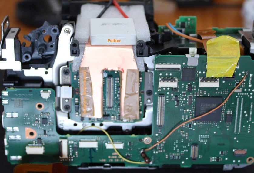
A copper sheet with a recess for the sensor cable leads upwards and then forwards into the area where the viewfinder was housed. The thermal contact between the copper sheet and the sensor board is provided by a thick thermal pad, which should fill the gap well. It is important to use a pad, not thermal paste, which conducts heat much worse. And it is not such a mess.
To be on the safe side, the copper sheet is insulated against electrical contact with the sensor with a thin adhesive tape. The copper is only 0.3mm thick, which is enough for the small amount of heat that needs to be transported. In general, it is very important to keep the amount of heat as low as possible, then a small amount of power is sufficient for the Peltier element. I chose a TEC 04901, a very 'weak' Peltier that draws a maximum current of 1A. However, its cooling power is sufficient for the desired purpose.
To be on the safe side, the copper sheet is insulated against electrical contact with the sensor with a thin adhesive tape. The copper is only 0.3mm thick, which is enough for the small amount of heat that needs to be transported. In general, it is very important to keep the amount of heat as low as possible, then a small amount of power is sufficient for the Peltier element. I chose a TEC 04901, a very 'weak' Peltier that draws a maximum current of 1A. However, its cooling power is sufficient for the desired purpose.
It is essential that the copper sheet is very well insulated from the outside, especially around the cable to the mainboard. PU foam and thin padding foil are well suited for this.
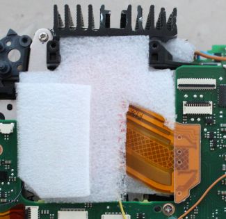
On top of the Peltier element sits the heat sink, cut to 35x45 mm² in size. A radial fan is then placed on top of this. A thin padding foil between fan and heat sink dampens possible vibrations of the fan and is cut in such a way that the air sucked in from the front and rear sides flows through the heat sink as effectively as possible.
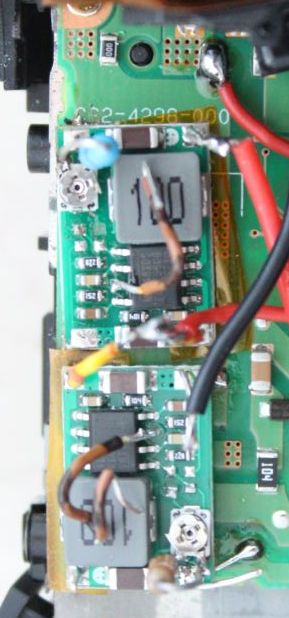
The Peltier element is powered by one of the popular small Mini360 bucks, which I soldered onto the power board of the camera instead of the flash capacitor. It is fed directly from the battery connection with 7.2 V. Since this voltage is permanently present, it is deactivated via the enable input on pin 7 of the IC when the camera is switched off. Next to the voltage trimmer, a resistor is soldered on that limits the maximum output voltage. The smoothed control voltage from a PWM output of the Arduino is then connected to this so that it can regulate the cooling performance.
The second Mini360 under the first regulates the voltage for the 5V fan down to about 3V, so that it then works without much noise and vibration.
Electronics
An Arduino Pro Mini forms the core of the entire control system. With its data pins D2-D4 and D6-D8, it works on emulating the shutter signals for the 2000D, from which it also receives its supply voltage of 3.3V, as does the HC-05 Bluetooth module, which it connects via D10 and D11. D10 and D11 emulate a serial interface in software. You can also connect the Bluetooth module to the built-in serial interface via D0 and D1 instead, but you then have to disconnect it every time you want to upload a new sketch to the Arduino.
An Arduino Pro Mini forms the core of the entire control system. With its data pins D2-D4 and D6-D8, it works on emulating the shutter signals for the 2000D, from which it also receives its supply voltage of 3.3V, as does the HC-05 Bluetooth module, which it connects via D10 and D11. D10 and D11 emulate a serial interface in software. You can also connect the Bluetooth module to the built-in serial interface via D0 and D1 instead, but you then have to disconnect it every time you want to upload a new sketch to the Arduino.
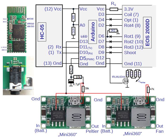
D9 is connected to the pin marked 'Shoot' in the picture of the cable release socket, which is located on the main board of the 2000D. This allows the Arduino hosted interval timer to trigger the camera.
D13 goes to the enable inputs of the two Mini360s to switch the cooling on and off and to automatically deactivate it when the camera is switched off. To prevent the Arduino LED, which is also connected to D13, from lighting up when the cooling is running, it must be desoldered or broken out.
D5 is used as a PWM output. The combination of two resistors and a capacitor connected to it smooths the square wave signal, which is then fed into the voltage control of the Mini360, which supplies the Peltier, and thus regulates the cooling performance. The control range is approximately 1V to 4V.
The additional resistors soldered to the Mini360 limit its output voltage to 5.2V (Peltier) or 4.6V (fan). They are not absolutely necessary.
To prevent the sensor from dewing, there are four resistors in the mirror box, each with 5.1Ω, which are fed by the Peltier voltage and thus heat in proportion to the cooling capacity. They can also be controlled by being gated via D12 and a MOSFET.
The temperature (of the copper cooling plate) is determined using an NTC thermistor. To do this, its voltage is measured at the A0 input of the Arduino. The second resistor at A0 should have the same value as the NTC at 25°C, which makes it easier to calculate the temperature from the measured voltage. I used a 10kΩ type here, but 100kΩ will also work.
Important: In order to upload a sketch, the camera must be switched on, as it supplies the Arduino. The supply via USB / Serial Breakout must not be connected in parallel to the Vcc of the camera!
Bluetooth Remote Control
The wiring with the Bluetooth module (an HC-05 or even better a DX-BT04 device) ,which has already been shown above, is quite simple. The question now is how best to communicate with it.
Fortunately, there are already numerous solutions available for this, i.e. apps that exchange data with Bluetooth devices on a cell phone or tablet. You could even put together your own app for this with a reasonable amount of effort, but I've made do with the "Serial Bluetooth Terminal" for now, although "made do" isn't really the right word, because it's a very nice app that does exactly what I need for the purpose. The Bluetooth related code on the Arduino side is part of the ShutterEmuEOS sketch. It is designed for the Bluetooth Terminal app and can be easily adapted if necessary.
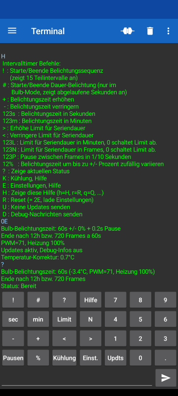
This screenshot of the Bluetooth Terminal shows the output of the help function, the current settings and the status of the camera in the upper half.
In the lower part of the screen the Bluetooth Terminal offers a configurable 'keypad'. Behind each key there is a macro that can be configured. Here the macros are designed so that they each send a character in order to easily execute the most important commands. Some commands expect a sequence of numbers that is entered before the command character.
The key configuration can also be exported to a file in order to edit it on the computer or import it onto other devices. A copy of this is included with the ShutterEmuEOS program.
In the left part of the keypad are the commands for the interval timer, which triggers series of images with freely selectable exposure times (and pauses). You can operate the camera in bulb mode as well as in all other modes in which the camera specifies the exposure time, for example to take time-lapse series.
At the bottom there is also the 'Kühlung' (i.e. Cooling) button, which is used to send the instructions for setting the cooling. For example, the character string '1K', which is sent with the '1' and 'Kühlung' keys, switches the cooling to the lowest level, while '8K' activates the PID controller, which keeps the temperature constant.
» Details
» Interval timer exposure functions
» Cooler control commands
Cooling effect
After switching on the cooling, the measured temperature drops very quickly, which doesn't say much at first because the temperature sensor is located next to the cooling plate. But the EXIF temperature of the images taken also starts to drop sharply with 2 to 3 minutes delay and returns to what the temperature sensor measures after 10 to 20 minutes. This is much more effective than I expected and at first I was therefore concerned that the EXIF temperature was not coming from the sensor itself, but rather from an NTC on the sensor board, and might no longer reflect the sensor temperature well with external cooling.
However, measuring the sensor's dark current noise shows that the sensor is actually significantly cooled, which matches well with the EXIF temperature. What then completely convinced me was the heavy fogging of the cooled sensor when I used the cooling outdoors for the first time. Based on my cooled 6D, which has a similar integrated cooler (with a cold finger directly at the sensor), I expected to get a maximum of one or two degrees below the ambient temperature and therefore initially did not install a window heater, which I now had to retrofit. With this, I then measured the following values on the temperature sensor, which are about half a degree below the EXIF temperatures:
| Cooling setting | 1K | 2K | 3K | 4K | 5K | 0K |
| PWM signal (D5) | 255 | 164 | 71 | 42 | 0 | - |
| Peltier voltage | 0.95V | 2V | 3.1V | 3.4V | 4V |
- |
| Peltier power | 0.25W | 1W | 2.5W | 3W | 3.8W | - |
| Window heating | 35mW | 66mW | 400mW | 460mW | 620mW | - |
| ΔT (with 60s Frames) | -1.4°C | -3.0°C | -4.8°C | -4.6°C | -5.0°C | +6.4°C |
This means you can get down to about 5°C below the ambient temperature, or even one degree more without window heating. Almost full cooling is achieved with 2.5 watts of Peltier power, but even with a quarter of a watt the sensor temperature remains significantly below the ambient temperature. To cool more deeply you would have to turn up the fan or make the heat sink bigger. Or you could stack two Peltiers, but that would require to create more space. And the SNR gain would be rather small. Even at an outside temperature of 20°C the dark current noise of the sensor, which is then 15°C warm, only reaches the readout noise after an exposure time of about 15 minutes.
With no cooling activated, the sensor heats up by around 7 degrees, or by around 11 degrees if no cooler is installed. The total temperature reduction compared to the unmodded camera is then 16 degrees.
Here is a series of measurements for cooling, in which the camera continuously recorded 60s frames, initially uncooled, then from frame 113 with 2.5W cooling power (with active window heating and display off):
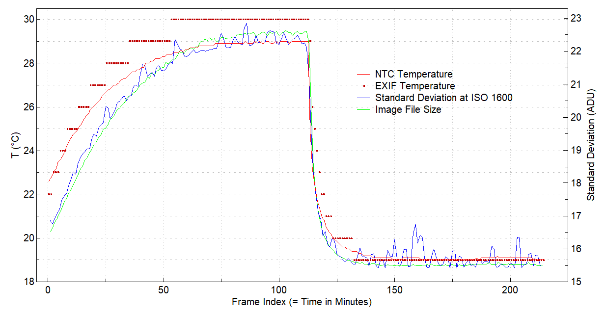
First, you can see that the temperatures from the NTC and the EXIF data of the images rise almost in parallel over an hour and then drop sharply when the cooling is switched on. The sensor follows the NTC with a delay of around 3 to 5 minutes. The fact that the standard deviation calculated from the images follows the temperature curve clearly indicates that the sensor temperature is actually falling substantially.
The standard deviation of bias frames, i.e. the noise without dark current contribution, is 13.5 ADU for this camera (at ISO 1600), which is too close to the measurement curve for an accurate evaluation. A comparison with 20-minute frames in which the dark current has a higher proportion of noise shows that the EXIF temperature reflects the sensor temperature well.
The size of the image files, which is also shown in the diagram, also follows the standard deviation very nicely.
From the distribution of the standard deviation over the sensor surface, you can see that the sensor temperature is fairly homogeneous. Even in the center below cable socket of the sensor, where the cooling plate does not reach, no higher temperature can be determined. Apparently the sensor really has very good heat conduction:
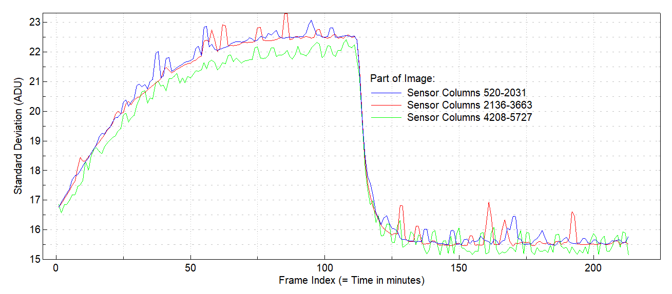
Although there is some difference between the areas in the left and right halves of the sensor, the center does not have a higher standard deviation than the left half of the sensor.
Conclusion
Contrary to my expectations, the sensors of the newer Canon cameras, which are soldered over the entire back-surface onto a circuit board, can be cooled quite well, even a little better than the older generation by a cold finger in the gap between the sensor and the circuit board.
In addition, it is much easier to do and you don't even have to unmount the sensor. Even with very low cooling power, the sensor temperature can be kept at ambient temperature or slightly below, so that the dark current remains within acceptable limits even in summer.
And of course the integrated control can keep the temperature constant, making the dark correction much easier and more reliable.
Update: Dew Point Detection
On a few nights in October I had the case that the sensor fogged up over the course of the night, even with the lowest cooling power. That's why I slightly modified the circuit for the window heater so that it heats more when the cooling is weak. And for better control of the heating, the Arduino has also been given a temperature and humidity sensor of the type AHT20, a small circuit board that is easy to accommodate and is addressed via the Arduino's I2C interface.
From the temperature and relative humidity the dew point can be calculated and thereby one can estimate at which temperature the sensor will fog up. This means I can now adapt the sensor heating to the current weather situation and reduce the cooling in the event of extreme humidity.
In the course of upgrading with the AHT20, I also changed the assignment of some control lines so that the pins D11, D12 and D13 required for the SPI interface on the Arduino, and A0 are freed. Instead of these, three of the analog pins, which can also be used digitally, are now used:

A3 now takes over the activation of the two Mini360s, while A1 and A2 establish the connection with the Bluetooth module. A4 and A5 form the I2C interface on which the AHT20 is connected. One of the four 5.1Ω resistors in the mirror box was replaced with two additional diodes, that direct the higher of the Peltier and fan voltages to the heating resistors. They are also placed in the mirror box, because they heat up like the resistors.
The Arduino's temperature control can either reduce the set cooling level directly if the sensor temperature falls below the dew point or, with PID control running, increase the target temperature if the dew point rises over the course of the night. Alternatively or in parallel, it can also be configured to adjust the heating output.
Finally, I plan to integrate a small memory module via the SPI interface of the Arduino (pins D11, D12 and D13) that has now been freed up, which will then allow me to update the software via Bluetooth so that I no longer have to open the camera if I want to adjust something.
Update: Software update for the Arduino via Bluetooth
A software update via Bluetooth has the great advantage that you don't have to open the camera to make improvements or extensions to the control program.
The prerequisite for this is a small external memory module of the SPI flash type, e.g. a W25Q32. Even a small size (32 MBit or 4MB) is completely sufficient.
Additionally, the Arduino bootloader must be replaced with a suitable variant of the more advanced 'urboot' bootloader. If this is set up correctly, the Arduino can be instructed to upload a new sketch to the external flash memory, which can then be installed by the bootloader after a reset.
A new sketch is compiled in the usual way and the resulting file "ShutterEmuEOS.ino.hex" is uploaded to the Arduino via Bluetooth. You may have to first transfer it to a device that can be connected to the Arduino. I send it by email to my smartphone, from where I then upload it using the 'Serial Bluetooth Terminal'.
But it also works under Windows if the computer supports Bluetooth. You can set up a (virtual) serial interface (e.g. COM9:) to which the Arduino has to be connected as a Bluetooth device. (See Windows Settings -> Devices -> Bluetooth and other devices -> More Bluetooth options -> 'COM Ports' tab -> Add Device -> Outgoing -> Device). With a terminal program that works via COM and can send files, such as 'RealTerm', you can now initiate and execute the upload.
The biggest challenge was installing the bootloader. For this I use Urboot together with MiniCore. MiniCore is a core for the Arduino that, together with Urboot, frees up almost 2 KB of program memory for your own sketches and can install Urboot directly. Unfortunately, it doesn't have the special "dual-boot" version of Urboot, which you have to install manually.
This is done with the program avrdude, which looks very complicated to call. The easiest way is to copy and adapt the calls that MiniCore makes in the Arduino IDE (with the setting 'Show verbose output during upload').
The first part of it looks something like this:
"C:/Users/XYZ/AppData/Local/Arduino15/packages/MiniCore/tools/avrdude/7.2-arduino.1/bin/avrdude"
"-CC:/Users/XYZ/AppData/Local/Arduino15/packages/MiniCore/hardware/avr/3.0.1/avrdude.conf"
and does not need to be changed. Then follow some settings that have already been adjusted:
-v -patmega328p -cstk500v1 -PCOM10 -b19200
and at the end there are the instructions on what to do, e.g.
-D "-Uflash:w:C:/Users/XYZ/AppData/Local/arduino/sketches/...../ShutterEmuEOS.ino.hex:i"
to load a Sketch, or
"-Uflash:w:urboot_m328p_1s_autobaud_uart0_rxd0_txd1_led+d5_csb0_dual_ee_ce_hw.hex:i"
-Ulock:w:0xff:m
to install a specific bootloader.
Unfortunately, MiniCore installs a so-called vector bootloader. This has the disadvantage that a sketch has to be modified before it is loaded, which avrdude usually takes care of. When uploading via Bluetooth, avrdude is not used, so you would have to patch the sketch yourself. That's why it's better to use a hardware-supported bootloader, ore on that below.
If a vector bootloader was installed (by MiniCore), one must reactivate the hardware support for the bootloader in the Arduino's processor. This is done by burning a so-called 'fuse' with the following instruction for avrdude:
-e -Ulock:w:0xff:m -Uefuse:w:0b11111101:m -Uhfuse:w:0xd6:m -Ulfuse:w:0b11110111:m
The various fuses are thus brought into the state that MiniCore sets in the standard setting (for BOD 2.7V) and minimum bootloader size, with the difference that hfuse receives the value 0xd6 instead of 0xd7, which activates the hardware support for the bootloader.
Selecting the bootloader
There is a huge supply of precompiled bootloaders in the urboot.hex repository. From this selection the ones that end in '_dual', for example "led+d5_csb0_dual", are suitable for an Arduino Nano or Pro-Mini.
The identifiers before the '_dual' describe which pins are used to control an LED ("led+" or "led-") and as a chip select (CS) of the SPI flash ("cs"). Here b0 denotes PB0 (= D8), b1 = PB1 = D9 and d5 = PD5 = D5.
The LED is not really of interest because it is being removed. (On the Pro-Mini or Nano board the LED is attached to D13 and therefore could not be used anyway because D13 controls the SPI flash.)
However, the LED pin should not conflict with the camera when configured as an output by the bootloader. In my 2000D I use D5 as PWM output. This makes the bootloader selection compatible with "led+d5" (or "led-d5"). D8, i.e. b0, is then left for the chip select. Under the "led+d5_csb0_dual" link you will find six variants, one of which ends with "_hw":
urboot_m328p_1s_autobaud_uart0_rxd0_txd1_led+d5_csb0_dual_ee_ce_hw.hex
If D8 is already being used for something else, there is an alternative with free pin selection, the template_dual variant, in which LED and CS are still without function. Here you have to insert (patch) suitable opcodes in the appropriate places so that the bootloader becomes 'dual'. The suitable variant is this:
urboot_m328p_1s_autobaud_uart0_rxd0_txd1_template_dual_ee_ce_hw.hex
The correct locations for CS instructions can be identified by the opcodes 0x2C55 to 0x2C99 of the instructions "mov r5,r5" to "mov r9,r9", which obviously don't do much. They need to be replaced by the appropriate port manipulation commands. Here is the example for PC0 alias Arduino A0 given by Stefan Rueger:
| Template opcode | Replacement | Comment | |||
| mov r5,r5 | sbi <port-C>, 0 | Set bit 0 of PORT C (release CS) | |||
| mov r6,r6 | cbi <port-C>, 0 | Clear bit 0 of PORT C (assert CS) | |||
| mov r7,r7 | sbi <ddr-C>, 0 | Set bit 0 of DDR C (make CS output) | |||
| mov r8,r8 | out <port-C>, r1 | Reset all PORT C bits: register R1 contains 0 | |||
| mov r9,r9 | out <ddr-C>, r1 | Reset all DDR C bits |
For the ATmega328P the address of PORT B/C/D is 5/8/11 and that of DDR B/C/D is 4/7/10.
(More information on patching template bootloaders.)
Without suitable tools, you have to put together the opcodes yourself. They are always 2-byte codes, with the first byte in the binary program in second place.
The second byte identifies the operands (bit-, port- or register-index):
sbi: 0x9A + 5 bits for the port register + 3 bits for the bit;
cbi: 0x98 + 5 bits for the port register + 3 bits for the bit;
out: 0xB8 + 4 bits for the source register + 4 bits for the I/O port.
Since hex files are plain text files, a text editor is a good choice for finding and replacing the opcodes.
These are the replacements I had to apply to the dual_template in order to define A0 (= PC0) as chip select:
|
Assembler Instruction |
Opcode | Hex |
replace by: |
|||
| mov r5,r5 | 0x2C55 |
552C |
sbi 8, 0 | 0x9A40 | 409A | |
| mov r6,r6 | 0x2C66 | 662C | cbi 8, 0 | 0x9840 | 4098 | |
| mov r7,r7 | 0x2C77 | 772C | sbi 7, 0 | 0x9A38 | 389A | |
| mov r8,r8 | 0x2C88 | 882C | out 8, r1 | 0xB818 | 18B8 | |
| mov r9,r9 | 0x2C99 | 992C | out 7, r1 | 0xB817 | 17B8 |
The 'hex' column indicates how the opcodes appear in a text editor. After replacement I saved the bootloader as
urboot_m328p_1s_autobaud_uart0_rxd0_txd1_no-led_csc0_patched_dual_ee_ce_hw.hex
Each line of a hex file ends with a checksum byte, which is now invalid for all the patched lines.
To avoid avrdude reporting errors and aborting, ":I" must be appended to the name of the hex file instead of ":i" as a format specifier.
This bootloader variant is available in the "ShutterEmuEOS\bootloader" directory together with
'Dual-Urboot_no-led_cs-A0-brennen.bat'. To prepare a new Arduino board, you need a programmer. In the Arduino IDE with Minicore selected you must then first select the correct controller type (ATMega328), the clock (8/16MHz external) and the variant (328/328P/328PB). Executing 'Burn Bootloader' now installs a basic Urboot variant.
By subsequently executing 'Dual-Urboot_no-led_cs-A0-brennen.bat', the dual urboot with chip select A0 is then burnt.
Special thanks to the authors of Urboot und MiniCore for their excellent software and their valuable help!
Initiating an Update
The 'F' commands are responsible for everything that has to do with flash memory:
"1F" initiates the transfer of a file, which must then be selected in the menu of the Serial Bluetooth Terminal with "Upload File" and sent. Because of the low transmission rate of 9600 baud, this takes approx. 2 to 3 minutes. Higher baud rates may not work if writing to the flash is too slow. First, the Serial Bluetooth Terminal reports that the upload is complete and some time later the camera should confirm that the sketch has been loaded and checked. Only now can commands be sent to the camera again that the camera would otherwise have considered as part of the upload!
"2F" activates the upload located in the external flash and causes the Arduino to be reset so that the bootloader can install the upload as a new control program.
Attention: New sketches should include the upload functions, otherwise the update capability will be lost!
The current version of the update functions now also manages a backup version.
If the camera switches off too quickly to perform an update due to an error in the shutter emulator, a camera with Magic Lantern activated can be caused by an SD card with the wrong ML version to permanently report this error.
Hardware
Finally, the connection diagram for the flash module. The last free pins besides D11-D13 were A6 and A7, which unfortunately cannot be used digitally with the ATMega328P. Therefore I had to resolder the NTC from A0 to A6 and use A0 as a chip select for the flash. To be on the safe side, I also removed the LED from the flash module.

Update: Backup Version for Bluetooth Updates
The first time I sent an update via Bluetooth to the reassembled camera, an error occurred that prevented further Bluetooth updates, and I had to open the camera again. So that this will not happen again so easily in the future, there is now the option of storing a backup version in external flash memory. This backup can then be activated with an 'F' command or, if the update does not work at all, it is automatically activated by the Arduino's watchdog. This activation is carried out analogously to the Bluetooth update by copying the code from its location in the SPI flash to the beginning of the SPI and then triggering a reset so that the bootloader finally transfers the code to the Arduino.
Last updated on February 11, 2025